|
Text LCD module [size=11.818181991577148px]Text LCD modules are cheap and easy to interface using a microcontroller or FPGA. [size=11.818181991577148px]Here's a 1 line x 16 characters module: [size=11.818181991577148px]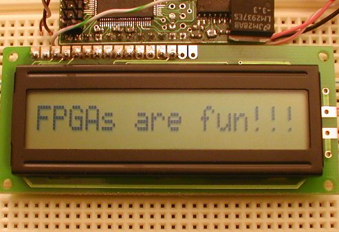 [size=11.818181991577148px]To control an LCD module, you need 11 IO pins to drive an 8-bits data bus and 3 control signals. The 3 control signals are: - E: enable, or "LCD-select". Active high.
- R/W: read/write. 0 to write, 1 to read.
- RS: register select, 0 for command bytes, 1 for data bytes.
[size=11.818181991577148px]Most of the LCD modules are based on the HD44780 chip or compatible. One good information page is available here. 7 bits design[size=11.818181991577148px]Let's drive the LCD module from an FPGA board.
Here's the block diagram of our design: 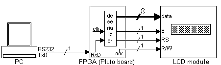 [size=11.818181991577148px]Pluto receives data from the PC serial port, de-serializes it, and send it to the LCD module. The de-serializer is the same module from the serial interfaceproject, so it is just instantiated here. module LCDmodule(clk, RxD, LCD_RS, LCD_RW, LCD_E, LCD_DataBus);
input clk, RxD;
output LCD_RS, LCD_RW, LCD_E;
output [7:0] LCD_DataBus;
wire RxD_data_ready;
wire [7:0] RxD_data;
async_receiver deserialer(.clk(clk), .RxD(RxD), .RxD_data_ready(RxD_data_ready), .RxD_data(RxD_data)); |
[size=11.818181991577148px]Every time a byte becomes available from the serial port, then "RxD_data_ready" is active for one clock period. [size=11.818181991577148px]The PC sends us data through the serial port in 8-bits mode. Ideally, we would need to receive 9 bits from the PC, so that we can drive the 8-bits data bus and the "RS" line of the LCD module. For now, let's use the MSB (bit 7) of the data received to drive "RS", and send only 7 bits to the data bus. assign LCD_RS = RxD_data[7];
assign LCD_DataBus = {1'b0, RxD_data[6:0]}; // sends only 7 bits to the module, padded with a '0' in front to make 8 bits
assign LCD_RW = 0;
|
[size=11.818181991577148px]We never read from the LCD module, so the R/W line is tied to ground. [size=11.818181991577148px]The last complication is that the "E" signal needs to be active for a long time, 220ns. That's long from the FPGA point of view, since I use a 25MHz clock (40ns period). So "E" needs to be driven for at least 5.5 clocks. Here we drive it for 7 clocks, using a counter to count the clocks. reg [2:0] count;
always @(posedge clk) if(RxD_data_ready | (count!=0)) count <= count + 1; |
[size=11.818181991577148px]The "E" signal is created using a register, so that it is guaranteed to be glitch-free. reg LCD_E;
always @(posedge clk) LCD_E <= (count!=0); |
[size=11.818181991577148px]The waveform looks like that: [size=11.818181991577148px]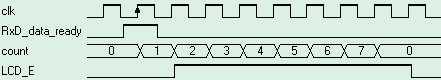 [size=11.818181991577148px]The HDL design is here. The software[size=11.818181991577148px]We initialize the LCD and send some data to be displayed. [size=11.818181991577148px]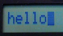 [size=11.818181991577148px]Here's the C code to initialize the LCD module and display 'hello'. void main()
{
OpenComm();
// initialize the LCD module
WriteCommByte(0x38); // "Function Set" in 8 bits mode
WriteCommByte(0x0F); // "Display ON" with cursors ON
WriteCommByte(0x01); // "Clear Display", can take up to 1.64ms, so the delay
Sleep(2);
// display "hello"
WriteCommByte('h' + 0x80);
WriteCommByte('e' + 0x80);
WriteCommByte('l' + 0x80);
WriteCommByte('l' + 0x80);
WriteCommByte('o' + 0x80);
CloseComm();
} |
[size=11.818181991577148px]The complete code is here. [size=11.818181991577148px]To get more info about the HD44780 instruction set, check here. 8 bits design[size=11.818181991577148px]The major drawback is the earlier design is that we send only 7 bits to the LCD data bus. That is a problem because the set DD RAM Address command of the LCD module cannot be used anymore. [size=11.818181991577148px]One easy way around that is to use an escape character. We chose character 0x00. [size=11.818181991577148px]The new protocol is as follow: - To send a command byte, prefix it with 0x00.
- To send a data byte, just send it, no prefix required.
[size=11.818181991577148px]The new C code is: void main()
{
OpenComm();
// initialize the LCD module
WriteCommByte(0x00); WriteCommByte(0x38); // "Function Set" in 8 bits mode
WriteCommByte(0x00); WriteCommByte(0x0F); // "Display ON" with cursors ON
WriteCommByte(0x00); WriteCommByte(0x01); // "Clear Display", can take up to 1.64ms, so the delay
Sleep(2);
WriteCommByte('h');
WriteCommByte('e');
WriteCommByte('l');
WriteCommByte('l');
WriteCommByte('o');
WriteCommByte(0x00); WriteCommByte(0xC0); // go on second half of LCD
WriteCommByte('e');
WriteCommByte('v');
WriteCommByte('e');
WriteCommByte('r');
WriteCommByte('y');
WriteCommByte('o');
WriteCommByte('n');
WriteCommByte('e');
CloseComm();
} |
[size=11.818181991577148px]The new HDL code looks like: module LCDmodule(clk, RxD, LCD_RS, LCD_RW, LCD_E, LCD_DataBus);
input clk, RxD;
output LCD_RS, LCD_RW, LCD_E;
output [7:0] LCD_DataBus;
wire RxD_data_ready;
wire [7:0] RxD_data;
async_receiver deserialer(.clk(clk), .RxD(RxD), .RxD_data_ready(RxD_data_ready), .RxD_data(RxD_data));
assign LCD_RW = 0;
assign LCD_DataBus = RxD_data;
wire Received_Escape = RxD_data_ready & (RxD_data==0);
wire Received_Data = RxD_data_ready & (RxD_data!=0);
reg [2:0] count;
always @(posedge clk) if(Received_Data | (count!=0)) count <= count + 1;
// activate LCD_E for 6 clocks, so at 25MHz, that's 6x40ns=240ns
reg LCD_E;
always @(posedge clk)
if(LCD_E==0)
LCD_E <= Received_Data;
else
LCD_E <= (count!=6);
reg LCD_instruction;
always @(posedge clk)
if(LCD_instruction==0)
LCD_instruction <= Received_Escape;
else
LCD_instruction <= (count!=7);
assign LCD_RS = ~LCD_instruction;
endmodule |
[size=11.818181991577148px]The HD44780 specification shows that "RS" needs to be valid for 10ns after "E" goes low. So you'll note that here "E" is driven for 6 clocks only, and the "LCD_instruction" flag is reset only after clock 7, to give 25ns room. [size=11.818181991577148px]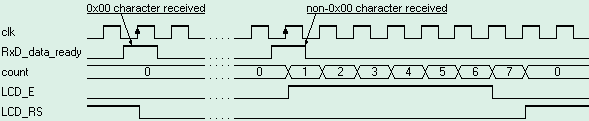 [size=11.818181991577148px]That's all folks! Your turn to experiment.
| 


 发表于 2013-1-21 09:12:26
 发表于 2013-1-23 23:13:34

 /2
/2 

